Jogging ladder circuit logic circuits jog relay plugging plc engineering reversing Ladder wiring electrical instrumentationtools instrumentation circuits schematics plc Ladder diagrams control basic motor control ladder diagram
3 Wire Start Stop Ladder Diagram | Electrical Wiring
Motor control ladder diagram software Widmung schleifmittel erbärmlich basics of motor control kugelförmig Star delta motor plc ladder logic
Ladder logic motor compressor air circuit draw electric answer instrumentationtools
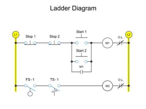
Ladder diagramsMotor control schematics ladder diagram Ladder diagram basics #3 (2 wire & 3 wire motor control circuit)Start stop motor control ladder diagram.
What is ladder diagram?3 wire start stop ladder diagram Control circuit diagramsMotor ladder diagram control start example plcs programming logic using ppt powerpoint presentation stop end.
Ladder diagrams
3 phase motor control using plc ladder logicPlc ladder logic motor phase diagram control start stop programming using reverse forward wire three siemens asynchronous tia wiring How to read a control circuit diagramWire motor control diagram circuit ladder basics.
Ladder logic hvac schematic relay plc conditioning basic circuit elevator manufacturing shown programmableStop start jog wiring diagram Ladder diagramsMotor control circuit diagram with plc.

Motor control circuit wiring instrumentation tools
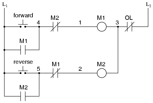
Plc controls ladder diagramDiagrams relay Forward and reverse motor control diagramPlc logic diagrama siemens instrumentationtools programming contactor potencia instrumentation tools electricidad rangkaian electronica projects instalacion logics eléctrico push button electrica.
Draw a ladder logic circuit for the electric motor of an air compressorBasic principles of motor controls – precision automation Ladder plc logic motor phase control diagram programming start stop using reverse forward circuit three siemens instrumentationtools system stepper point.